This tutorial will provide information about how to identify a normal stepper motor pin-out, and how to connect the wires to the labeled stepper-driver output module plugs.
Note 2-phase bipolar NEMA17 stepper motors like the JK42HM48-1684 (0.9 deg/step, 1.68A per field, 4.4kg/cm hold torque 'ideal') usually come with only a 4-wire lead, and a JST XH 2.5mm 4-Pin Female Connector at the end of the lead wires. However, like many popular items there are countless variations that share the same model number, but vary in the type of connectors, actual ratings, and wire color codes.
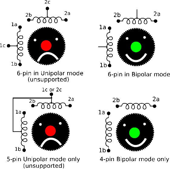
Often some NEMA17 motor models will have a JST XH 2.5mm 6-Pin male Connector socket on the motor itself, and while this does simplify some assemblies it is known to work free under heavy mechanical vibration (note, P-clips or cable ties will help with wire strain relief). The 6-pin or 6-wire stepper motors can use two common drive methods known as Unipolar mode and Bipolar modes. Note the diagram shows several common wiring variations that are possible, and specifies which configurations are supported by 2-phase bipolar stepper-driver modules.

Note, that I have not yet specified colors of the wires given several possibilities exist, and this text is meant to help people figure out what is already on a mechanism without having full component documentation.
- Tape the exposed wires onto a plastic or glass surface
- Ensure the machine is powered down, and unplugged
- Place your multi-meter into Ohmmeter mode
- Touch the Ohmmeter metal probes together to confirm it shows near 0 Ohms to confirm equipment is functional
- Measure the motor winding's field Resistances on each possible pair of wires by touching the meter probes to each exposed metal areas of the motor wires.
- Label the pairs with a diagram denoting the pairs resistance in ohms
- Don't forget to turn your meter back off
- Create a wire label chart for the motor model the machine is using
Note in the next example we assume the full bipolar winding's wire resistance ( 1a to 1b, or 2a to 2b) will be twice whatever a center-tap combination of wires shows. This makes sense in most cases, as we must isolate the center-taps (1c and 2c) given they are not used in a bipolar 2-phase stepper driver configuration. Note the subtle difference in the top-right of the illustration, as it shows the center taps are not connected in this configuration. Therefore these center taps will often not even have wires attached from some suppliers, and a 6pin motor is commonly driven with only 4 lines in the bipolar mode.
| Find unknown 6-pin Socket pin-out example: | |
| Probe Blk pin 1 and Red pin 2 | 0.825 Ohms (seems low, so probably a center tap 1c) |
| Probe Blk pin 1 and Red pin 3 | 1.65 Ohms (assume 1a and 1b candidate) |
| Probe Blk pin 1 and Red pin 4 | inf Ohms (note winding 1 not attached to winding 2) |
| Probe Blk pin 4 and Red pin 5 | 0.825 Ohms (seems low, so probably a center tap 2c) |
| Probe Blk pin 4 and Red pin 6 | 1.68 Ohms (assume 2a and 2b candidate) |
| Probe Blk pin 5 and Red pin 6 | 0.825 Ohms (confirms the center tap 2c on pin 5) |
Note the 6-pin example allows us to discover the bipolar configuration, but without the suppliers documentation we still have a 25% chance of which phase is truly 1 and not wired backwards. However, there is an interesting property of bipolar stepper drivers we are lucky to learn today. If you reverse the polarity of one of the full phase fields a stepper motor changes direction for the same drive pattern (for example: motor 1a to 1b on driver, and motor 1b to 1a of driver). This means equipment repair is easier without having to alter the software and or firmware of the motor drive logic.
